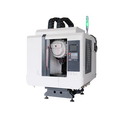


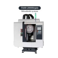
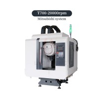

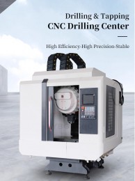
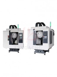


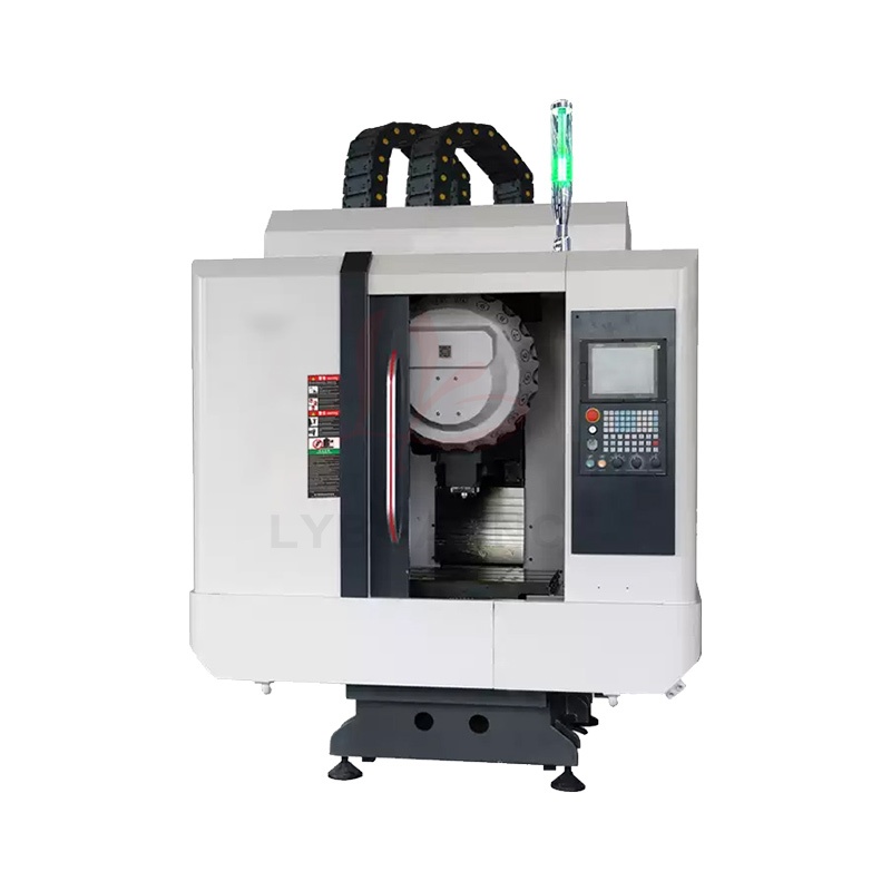
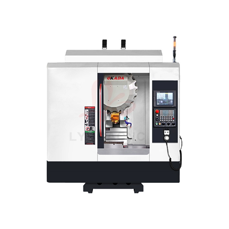
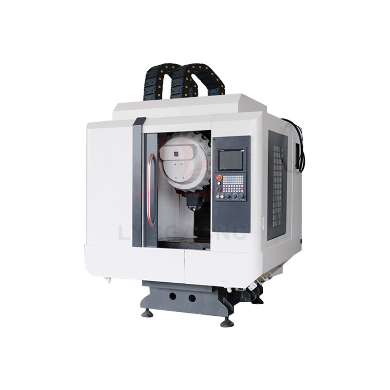
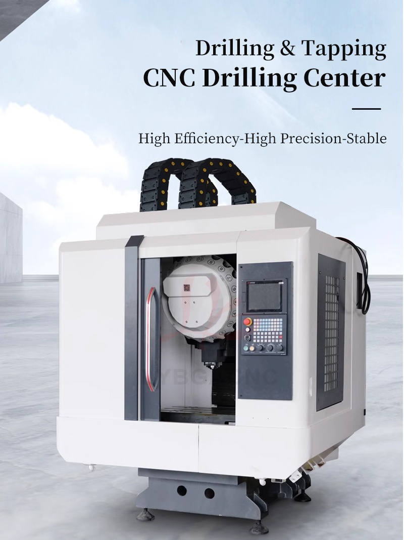
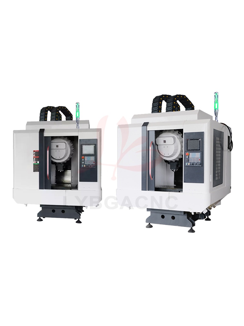
Drilling & Tapping Centers T-600 T-700 Water-cooled CNC Milling Machines For Drilling Tapping Milling Faces Mitsubishi System
 Reviews(0)
Product Detail
Product Tags
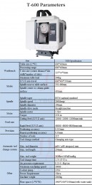
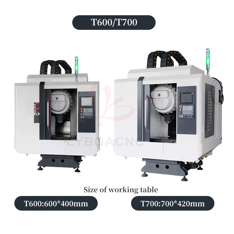
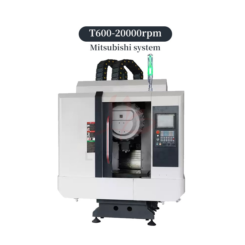
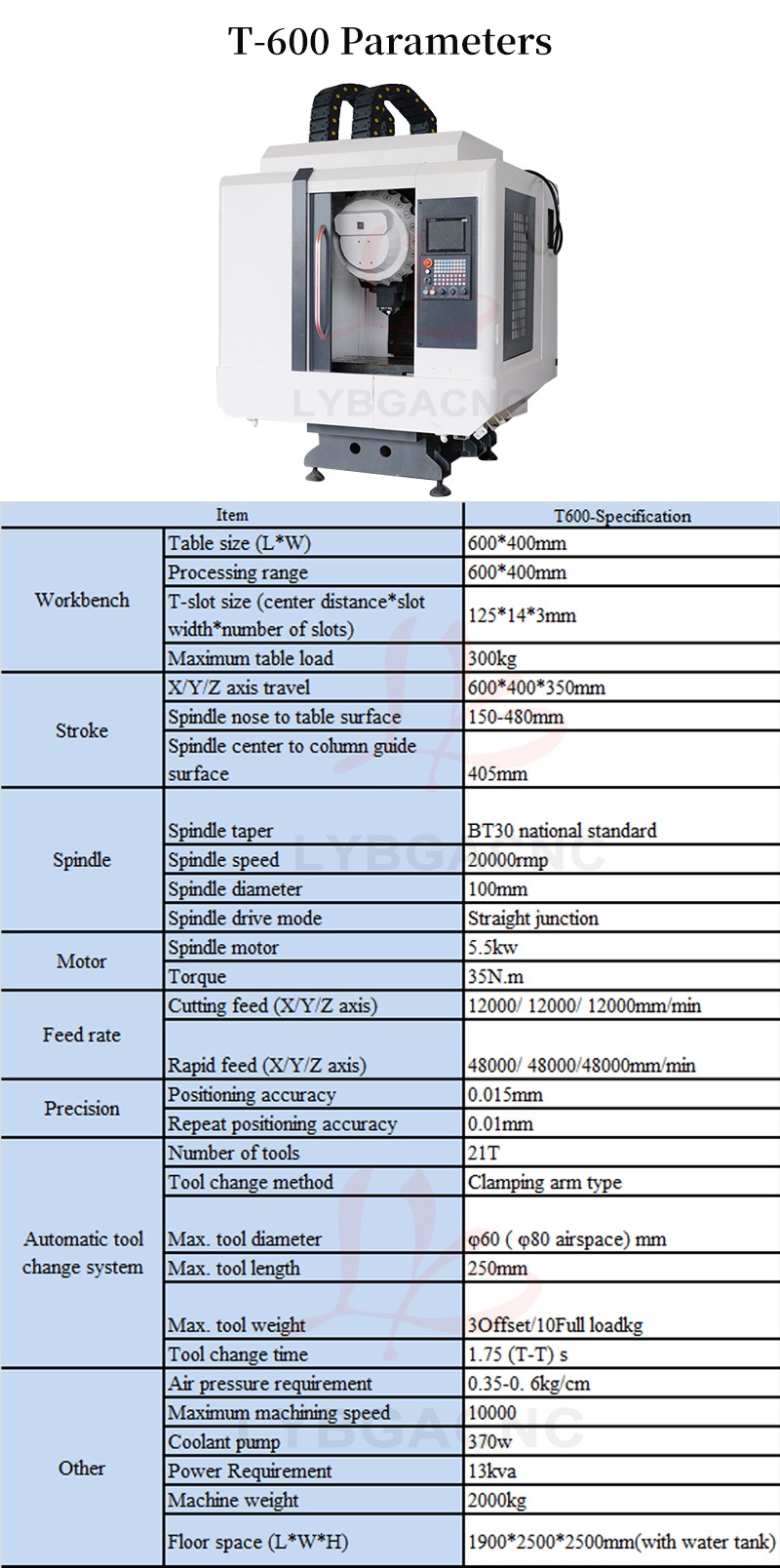
T-600
|
Item |
T600-Specification |
|
|
Workbench |
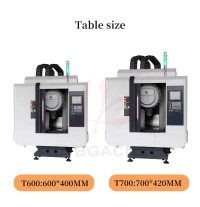
Table size (L*W) |
600*400mm |
|
Processing range |
600*400mm |
|
|
T-slot size (center distance*slot width*number of slots) |
125*14*3mm |
|
|
Maximum table load |
300kg |
|
|
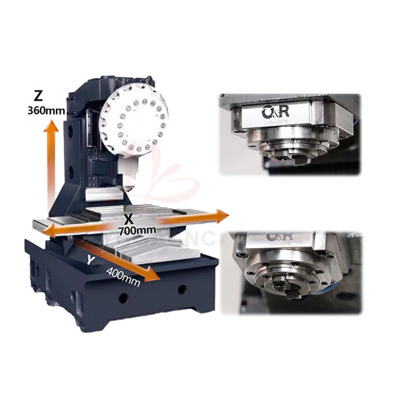
Stroke |
X/Y/Z axis travel |
600*400*350mm |
|
Spindle nose to table surface |
150-480mm |
|
|
Spindle center to column guide surface |
405mm |
|
|
Spindle |
Spindle taper |
BT30 national standard |
|
Spindle speed |
20000rmp |
|
|
Spindle diameter |
100mm |
|
|
Spindle drive mode |
Straight junction |
|
|
Motor |
Spindle motor |
5.5kw |
|
Torque |
35N.m |
|
|
Feed rate |
Cutting feed (X/Y/Z axis) |
12000/ 12000/ 12000mm/min |
|
Rapid feed (X/Y/Z axis) |
48000/ 48000/48000mm/min |
|
|
Precision |
Positioning accuracy |
0.015mm |
|
Repeat positioning accuracy |
0.01mm |
|
|
Automatic tool change system |
Number of tools |
21T |
|
Tool change method |
Clamping arm type |
|
|
Max. tool diameter |
φ60 ( φ80 airspace) mm |
|
|
Max. tool length |
250mm |
|
|
Max. tool weight |
3Offset/10Full load kg |
|
|
Tool change time |
1.75 (T-T) s |
|
|
Other |
Air pressure requirement |
0.35-0. 6kg/cm |
|
Maximum machining speed |
10000 |
|
|
Coolant pump |
370w |
|
|
Power Requirement |
13kva |
|
|
Machine weight |
2000kg |
|
|
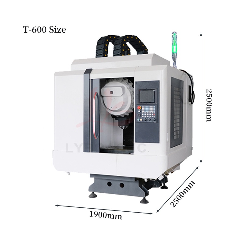
Floor space (L*W*H) |
1900*2500*2500mm(with water tank) |
|
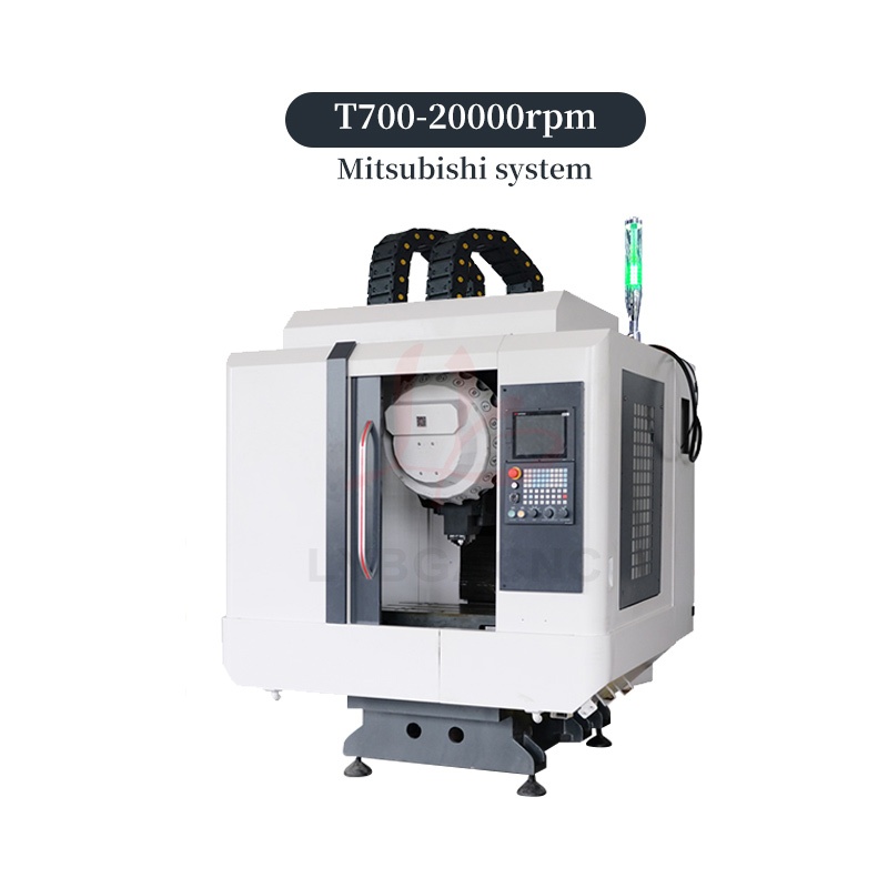
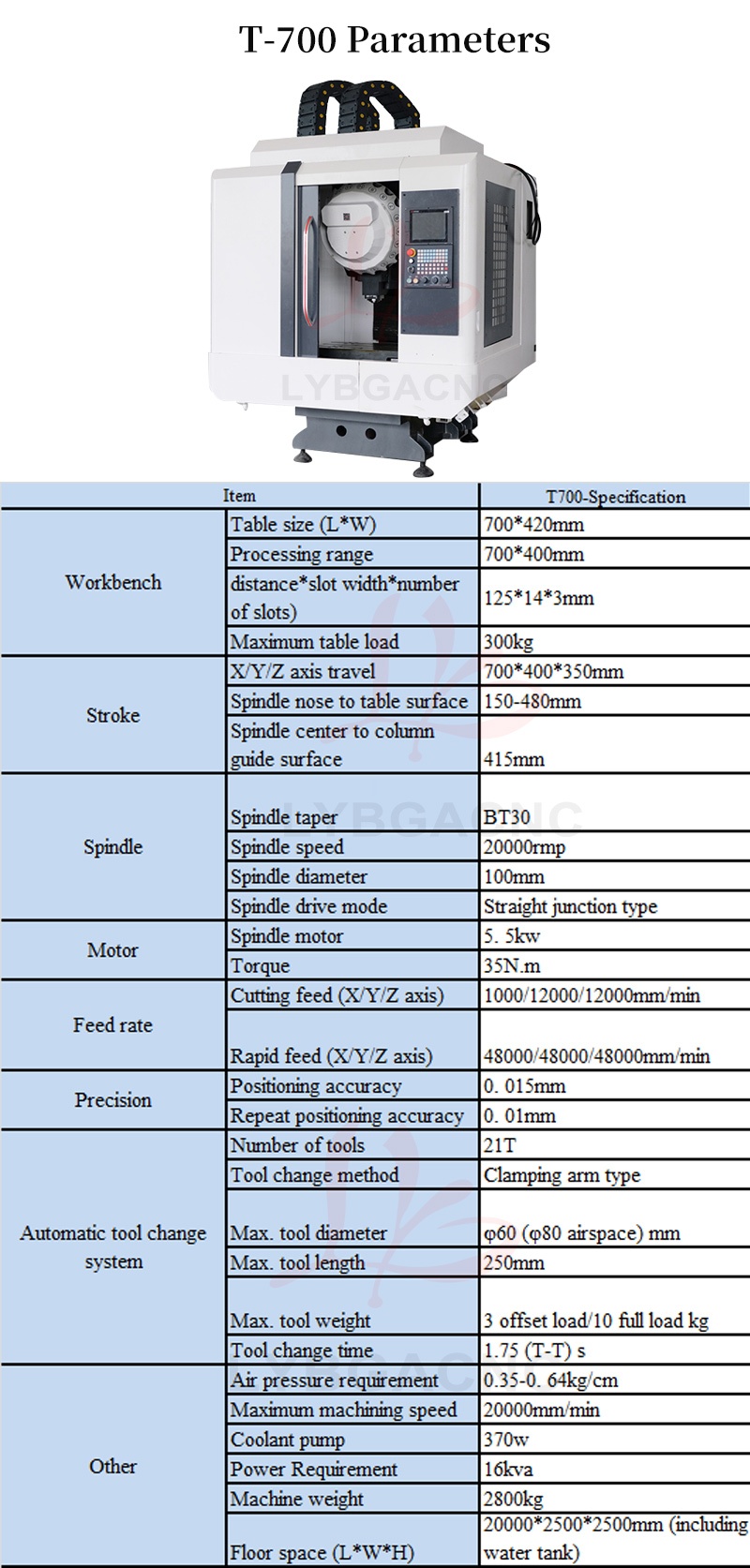
T-700
|
Item |
T700-Specification |
|
|
Workbench |
Table size (L*W) |
700*420mm |
|
Processing range |
700*400mm |
|
|
T-slot size (center distance*slot width*number of slots) |
125*14*3mm |
|
|
Maximum table load |
300kg |
|
|
Stroke |
X/Y/Z axis travel |
700*400*350mm |
|
Spindle nose to table surface |
150-480mm |
|
|
Spindle center to column guide surface |
415mm |
|
|
Spindle |
Spindle taper |
BT30 |
|
Spindle speed |
20000rmp |
|
|
Spindle diameter |
100mm |
|
|
Spindle drive mode |
Straight junction type |
|
|
Motor |
Spindle motor |
5. 5kw |
|
Torque |
35N.m |
|
|
Feed rate |
Cutting feed (X/Y/Z axis) |
1000/12000/12000mm/min |
|
Rapid feed (X/Y/Z axis) |
48000/48000/48000mm/min |
|
|
Precision |
Positioning accuracy |
0. 015mm |
|
Repeat positioning accuracy |
0. 01mm |
|
|
Automatic tool change system |
Number of tools |
21T |
|
Tool change method |
Clamping arm type |
|
|
Max. tool diameter |
φ60 (φ80 airspace) mm |
|
|
Max. tool length |
250mm |
|
|
Max. tool weight |
3 offset load/10 full load kg |
|
|
Tool change time |
1.75 (T-T) s |
|
|
Other |
Air pressure requirement |
0.35-0. 64kg/cm |
|
Maximum machining speed |
20000mm/min |
|
|
Coolant pump |
370w |
|
|
Power Requirement |
16kva |
|
|
Machine weight |
2800kg |
|
|
Floor space (L*W*H) |
20000*2500*2500mm (including water tank) |
|
详情页信息
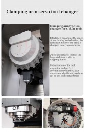
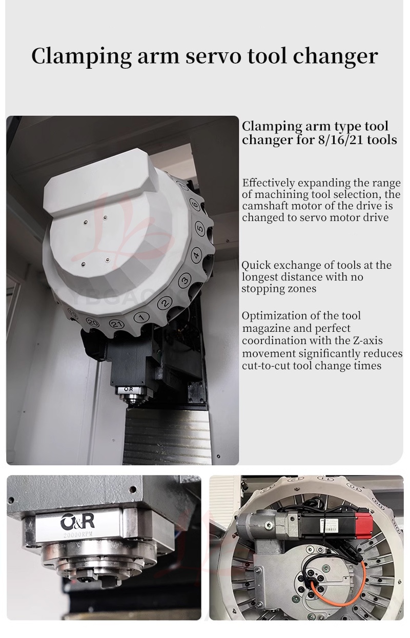
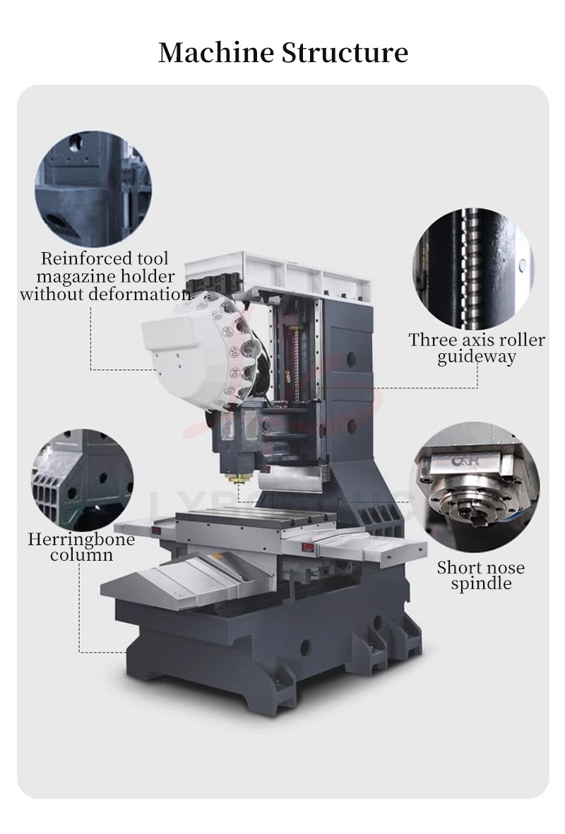
Clamping arm servo tool changer
Clamping arm type tool changer for 8/16/21 tools
1. Effectively expanding the range of machining tool selection, the camshaft motor of the drive is changed to servo motor drive
2. Quick exchange of tools at the longest distance with no stopping zones
3. Optimization of the tool magazine and perfect coordination with the Z-axis movement significantly reduces cut-to-cut tool change times
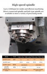
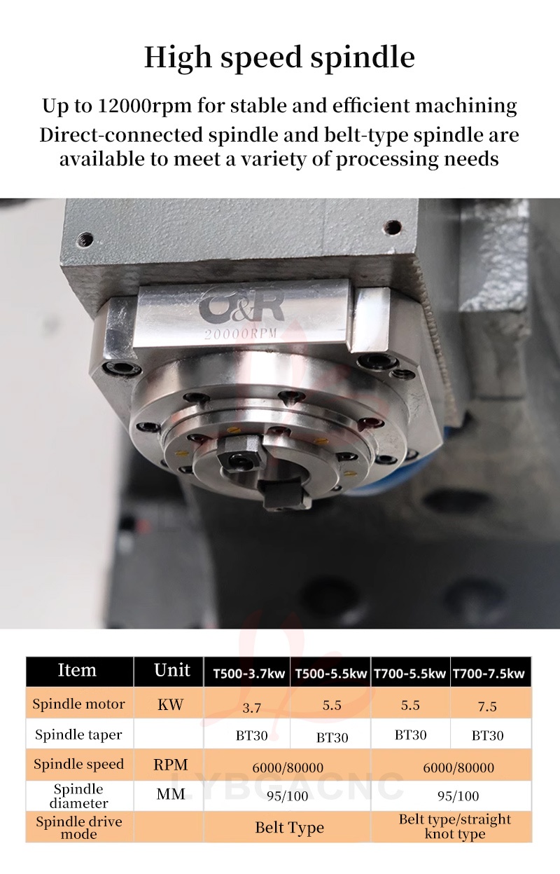
High speed spindle
Up to 12000rpm for stable and efficient machining
Direct- connected spindle and belt-type spindle are available to meet a variety of processing needs
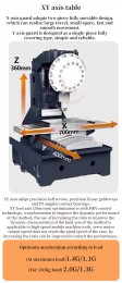
XY axis table
X-axis guard adopts two-piece fully movable design, which can realize large travel, small space, fast and smooth movement.
Y-axis guard is designed as a single- piece fully covering type, simple and reliable.
XY axes adopt precision ball screws, precision linear guideways and P3 angular contact bearings.
XY feed axis (20m/min) optimization is with HRV control technology, transformation to improve the dynamic performance of the method, the use of increasing the ratio to improve the dynamic characteristics of the feed axis of the method is applicable to high-speed mobile machine tools, servo motor output speed does not reach the rated speed of the case, by increasing the ratio can be improved to match the performance.
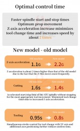
Optimum acceleration according to load
(At maximum load)1 .4G/1.1G
(For 150Kg load) 2.0G/1.3G
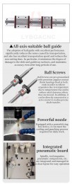
All-axis suitable ball guide
The adoption of ball guide with excellent performance significantly reduces the noise caused by transportation, and also has excellent transportation speed and reduces the non-cutting time. In particular, it minimizes the degree of damage to the slide and guideway surfaces, and maintains accuracy even after long periods of use.
Ball Screws
Ball Screws are pre-pressurized with precision angular contact thrust bearings fixed at both ends in order to relieve expansion due to temperature due to temperature rise and to reduce axial clearance when they are moved. In addition, it can be directly connected to a servo motor to realize precise shaft transfer.
Powerful nozzle
Equipped with a powerful ring box device, it can meet the cooling and punching process required for daily work.
Integrated pneumatic board
Spindle, tool magazine, pneumatic components, etc. are integrated and managed in a clear layout for easy operation
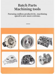
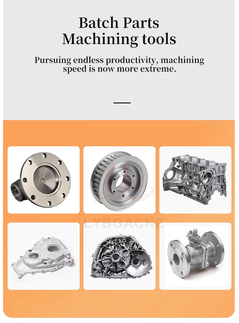
Batch Parts
Machining tools
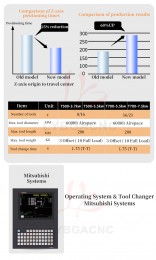
Pursuing endless productivity, machining speed is now more extreme.
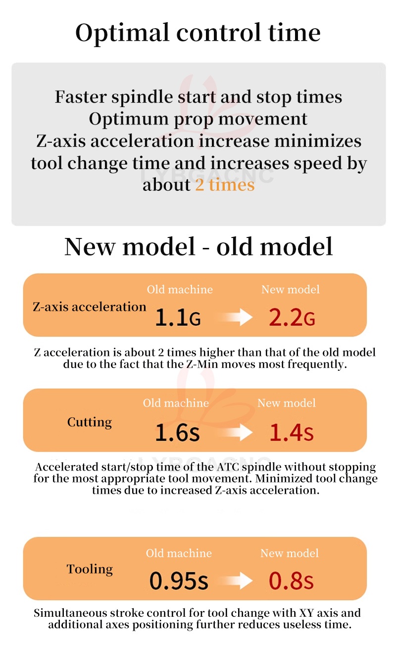
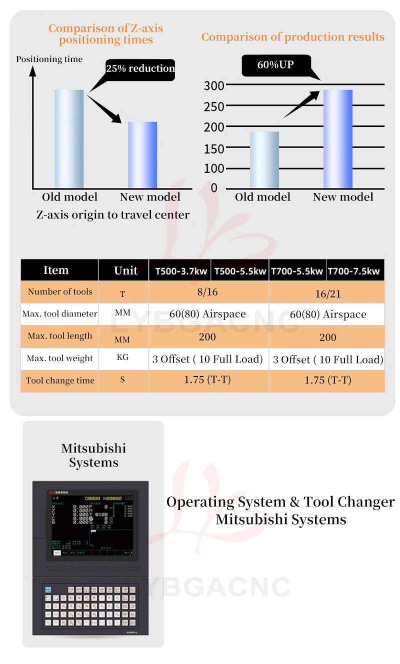
Optimal control time
Faster spindle start and stop times
Optimum prop movement
Z-axis acceleration increase minimizes tool change time and increases speed by about 2 times
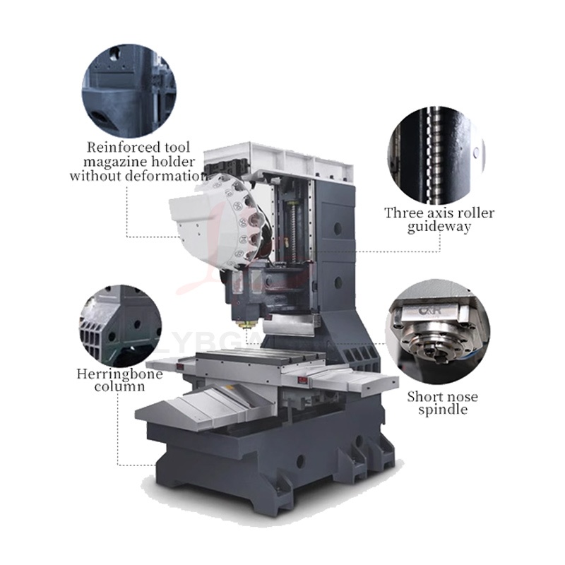
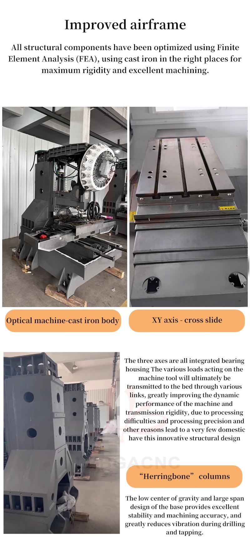
Improved airframe
All structural components have been optimized using Finite
Element Analysis (FEA), using cast iron in the right places for maximum rigidity and excellent machining.
Optical machine cast iron body
XY axis – cross slide
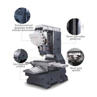
The three axes are all integrated bearing housing The various loads acting on the machine tool will ultimately be transmitted to the bed through various links, greatly improving the dynamic performance of the machine and transmission rigidity, due to processing dificulties and processing precision and other reasons lead to a very few domestic have this innovative structural design
Herringbone columns
The low center of gravity and large span design of the base provides excellent stability and machining accuracy, and greatly reduces vibration during drilling and tapping.
Thanks for your order!
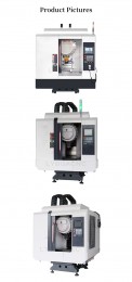
Product Pictures


Questions, issues or concerns? I'd love to help you!